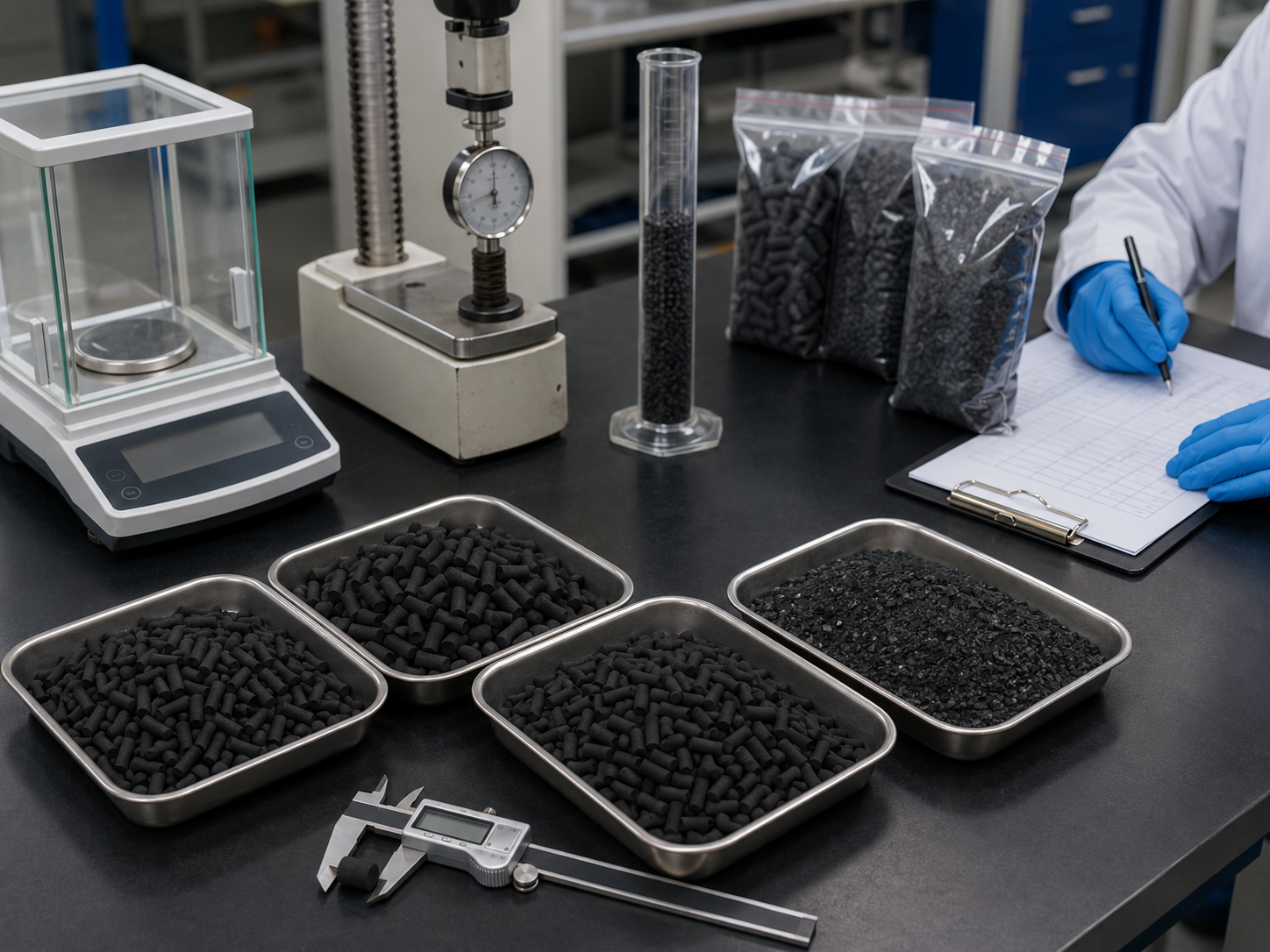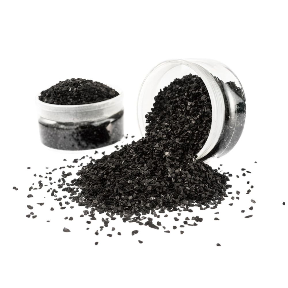
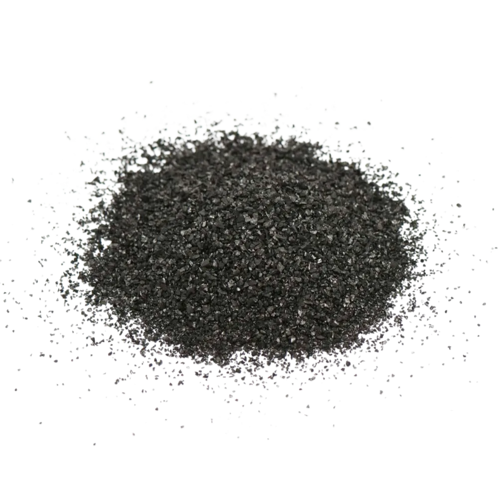
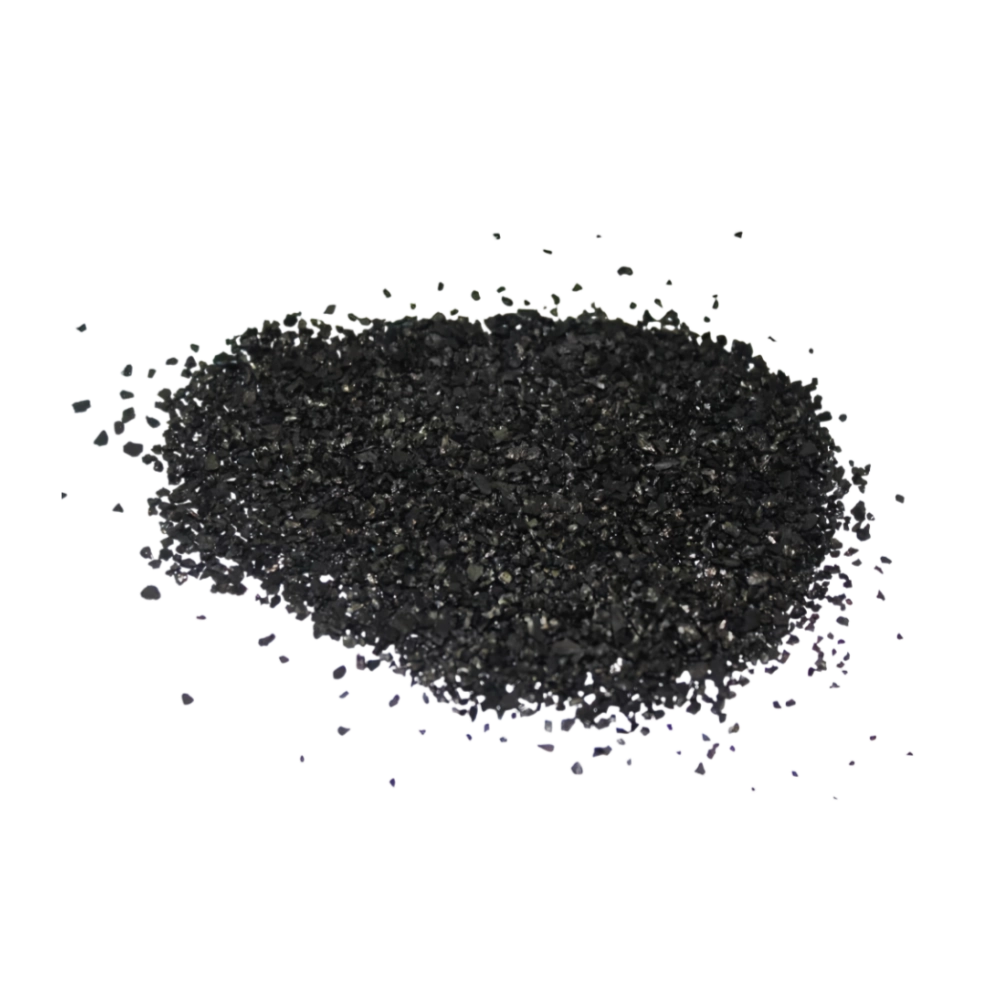
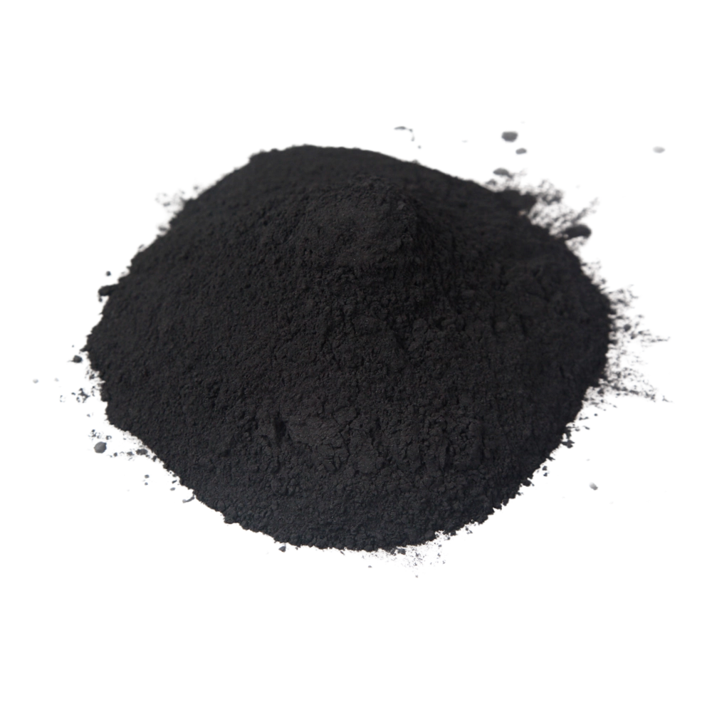
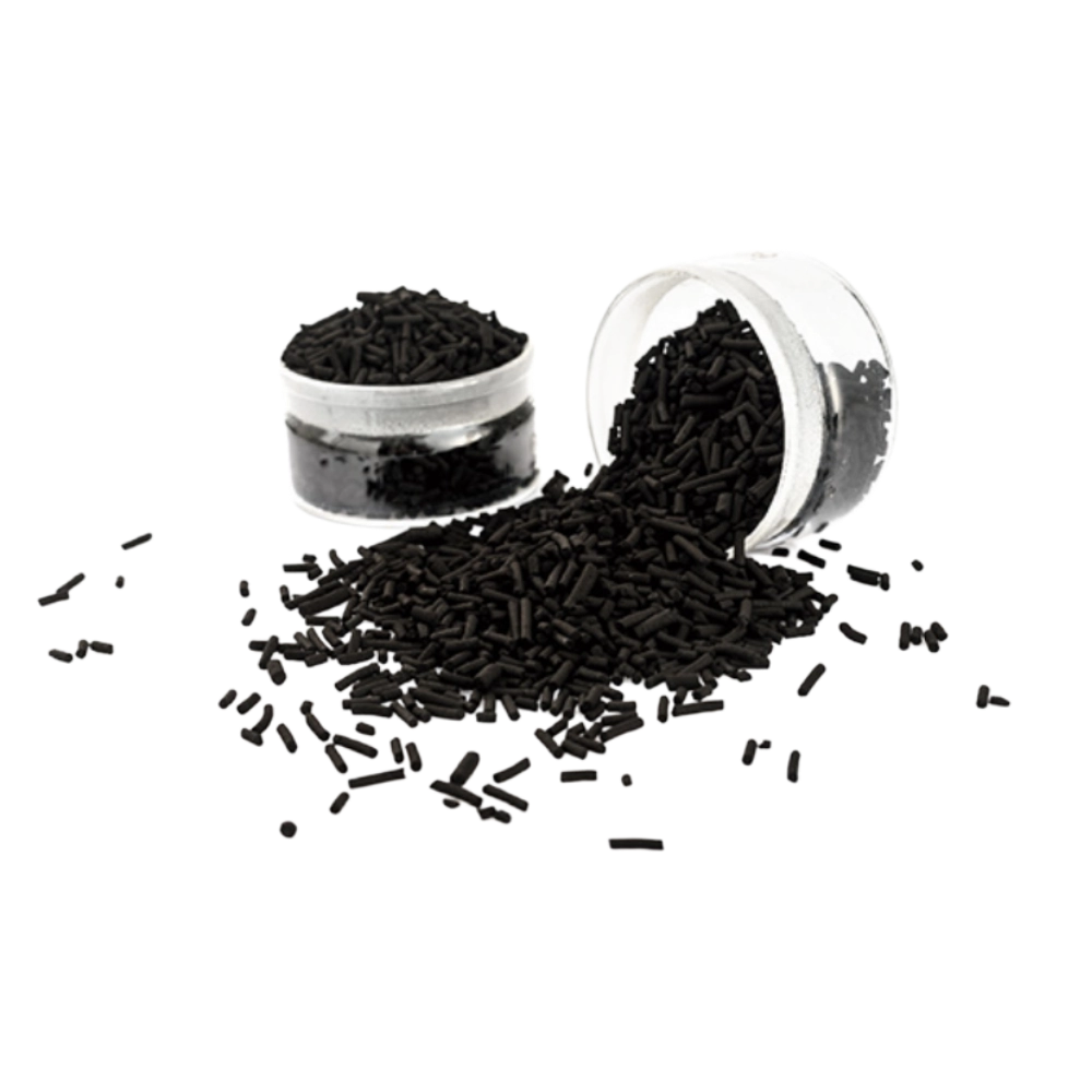
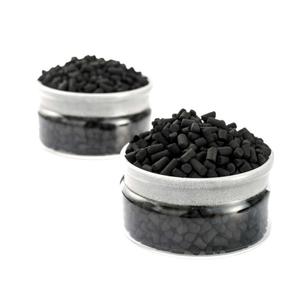
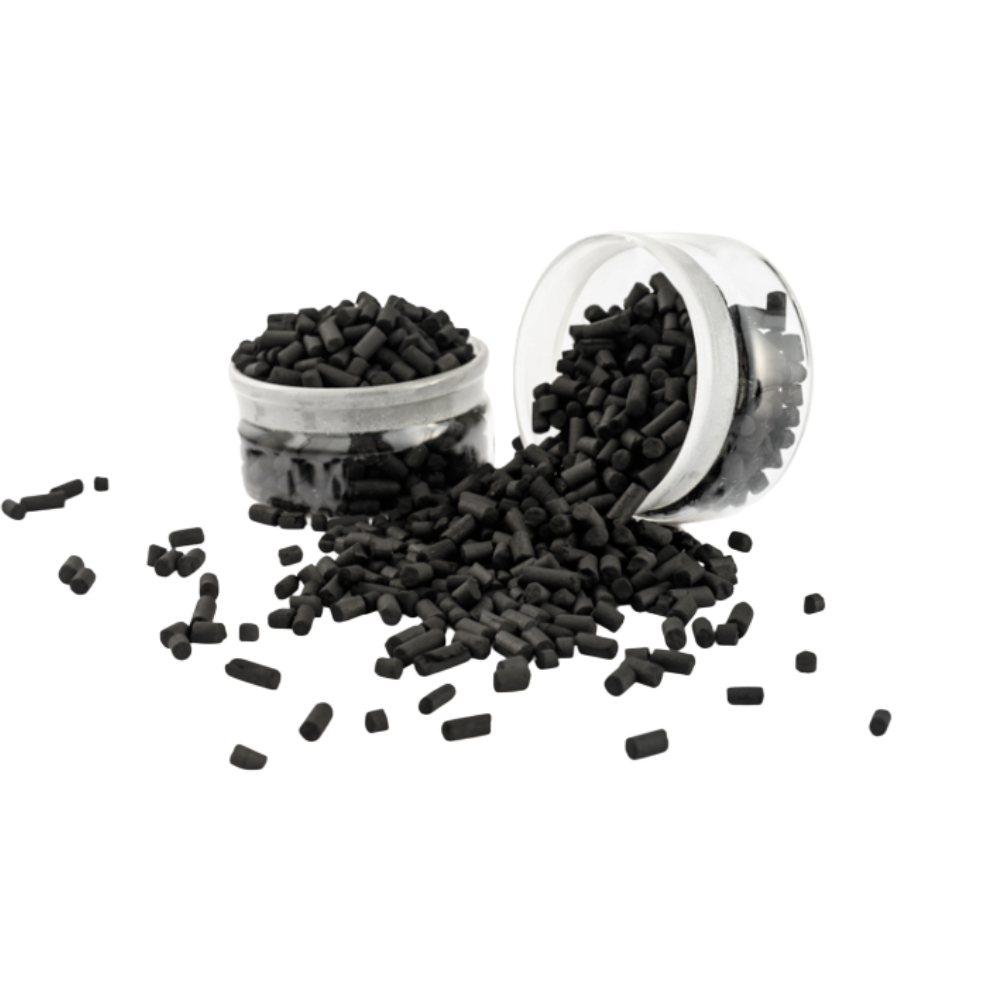
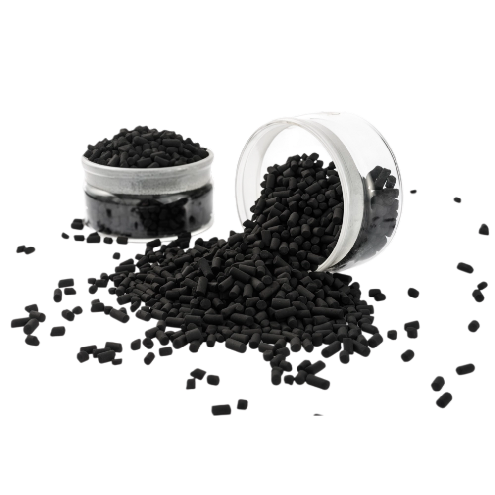
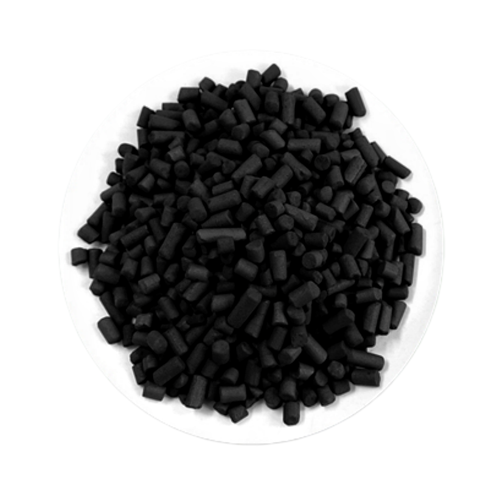
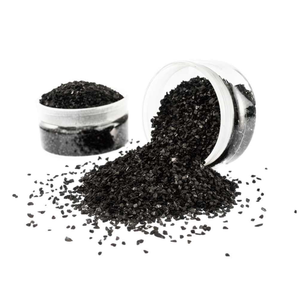
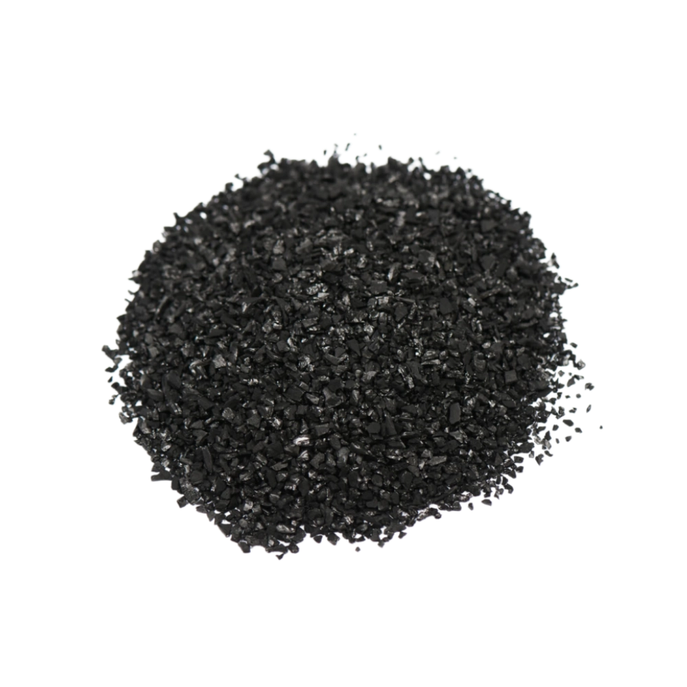
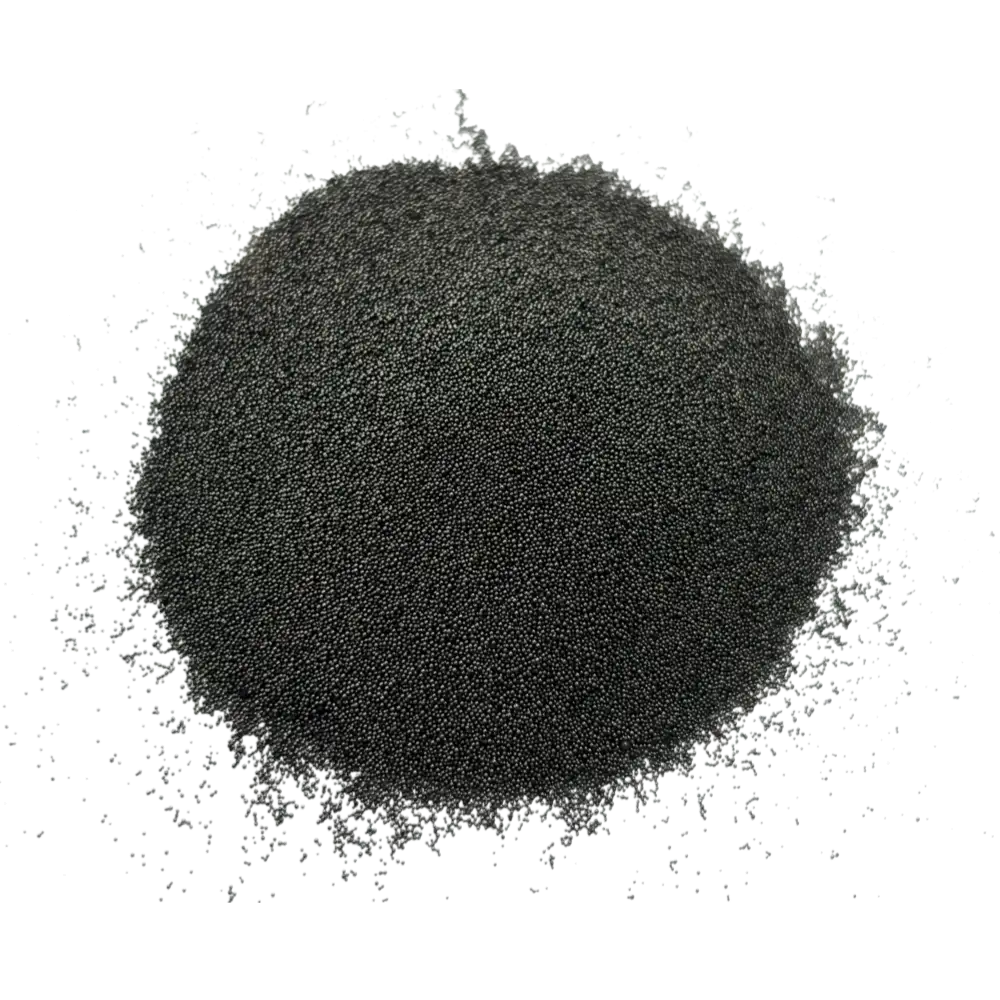
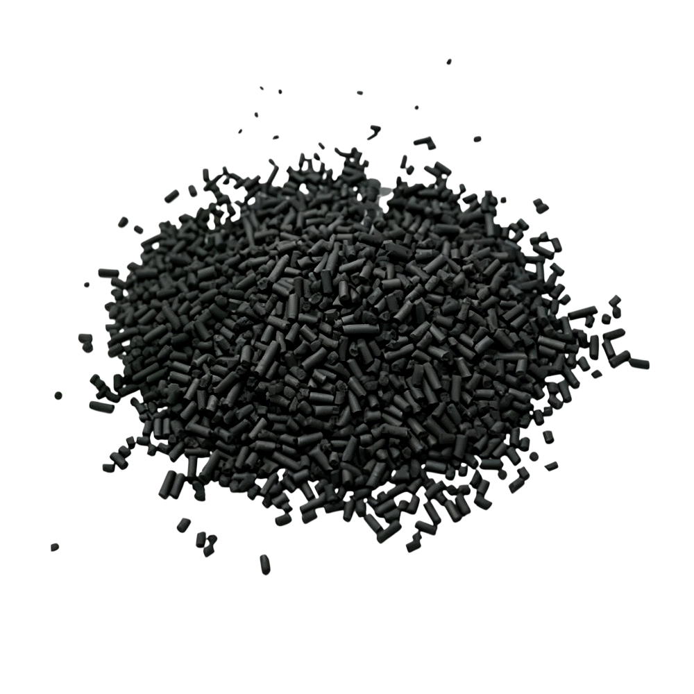
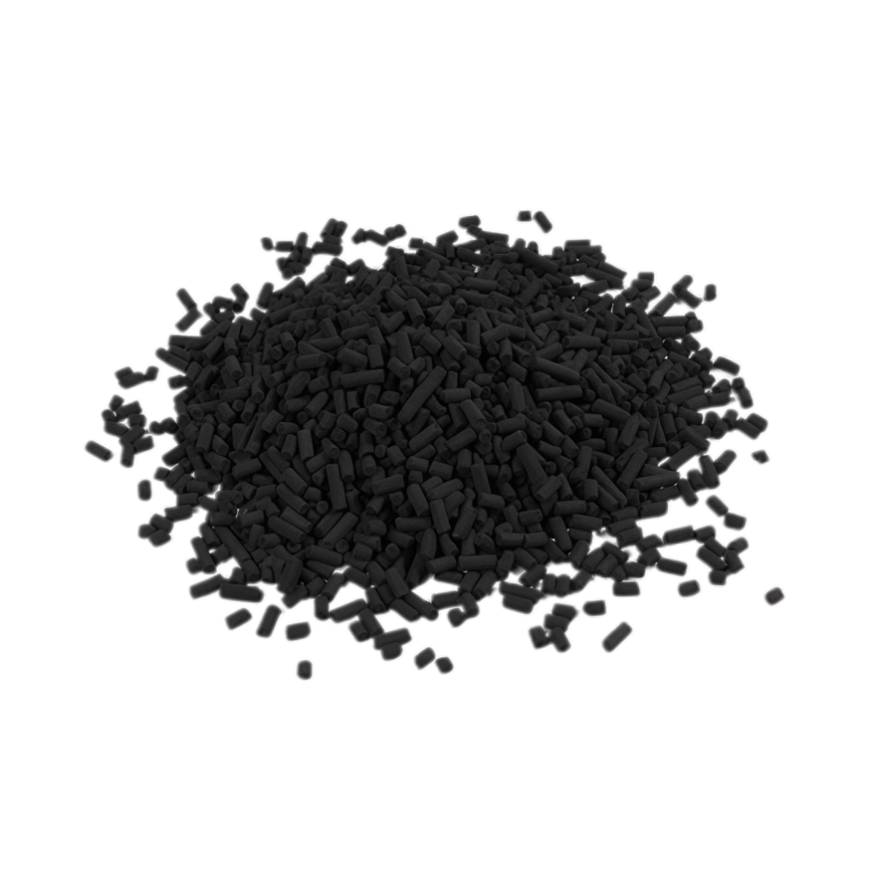
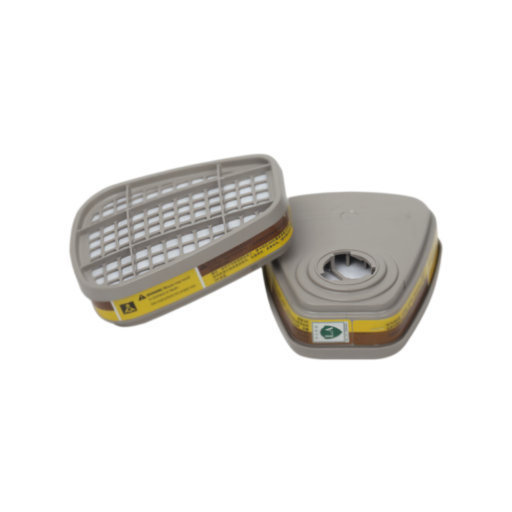






























An industrial carbon bed was expected to operate for six months. Eight weeks later, the outlet VOC concentration began to rise.
The immediate response is often to order a higher-activity carbon. That may help when the original media was underspecified, but early activated carbon breakthrough is frequently caused by changing VOC loads, excessive humidity, high temperature, insufficient contact time, bed channeling or contamination upstream of the adsorber.
Replacing the carbon without finding the cause may restore removal temporarily. The next bed, however, can fail just as quickly.
This article explains the eight most common causes of VOC carbon bed breakthrough, how to investigate them and what operating information is needed before selecting replacement activated carbon.
What Is Activated Carbon Breakthrough?
Activated carbon removes volatile organic compounds by adsorbing VOC molecules onto the internal surfaces of its pore structure.
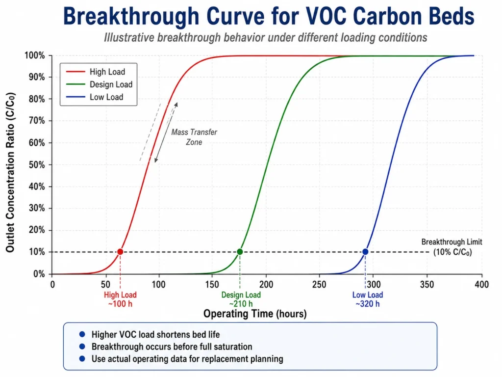
As contaminated gas enters a fixed carbon bed, the inlet section begins loading first. The active adsorption region then moves through the bed toward the outlet. This moving region is generally described as the mass transfer zone.
Breakthrough occurs when the target VOC concentration at the adsorber outlet reaches a defined limit.
That limit may be:
- An environmental emission limit
- A process-quality requirement
- A workplace exposure target
- A percentage of the inlet concentration
- A customer-defined replacement point
Breakthrough does not necessarily mean that every carbon pellet is completely saturated. It means that the bed can no longer maintain the required outlet concentration under the current operating conditions.
Three Capacity Terms That Buyers Should Not Confuse
| Term | Practical meaning |
|---|---|
| Equilibrium or saturation capacity | The maximum amount that carbon may hold under defined equilibrium conditions |
| Breakthrough capacity | The amount adsorbed before the outlet reaches a specified concentration |
| Working capacity | The usable capacity available during an actual operating or regeneration cycle |
For industrial VOC systems, working capacity and breakthrough capacity are generally more useful than a maximum laboratory activity value.
Facilities designing or reviewing a treatment system can first examine PureStar’s activated carbon solutions for industrial VOC treatment.
Quick Diagnosis: What Does the Breakthrough Pattern Suggest?
The way outlet VOC concentration changes can provide an early indication of the underlying problem.
| Operating symptom | Likely areas to investigate |
|---|---|
| Outlet VOC rises gradually after a normal operating period | Normal exhaustion or insufficient installed carbon capacity |
| Outlet VOC rises during production peaks | Higher-than-designed VOC mass loading |
| Fresh carbon performs poorly immediately | Bypass, insufficient contact time, incorrect media or measurement error |
| Service life falls after changing raw materials | VOC composition or concentration has changed |
| Removal falls as pressure drop increases | Dust, oil mist, condensation or excessive fines |
| Outlet concentration fluctuates sharply | Process instability, channeling, leakage or analyzer issues |
| Some carbon is heavily loaded while other areas remain relatively clean | Uneven airflow or poor bed distribution |
| Regenerated carbon delivers progressively shorter cycles | Incomplete regeneration, fouling or reduced remaining working capacity |
This table is a starting point. A reliable diagnosis still requires operating data and a physical inspection of the system.
Eight Causes of Early VOC Carbon Bed Breakthrough
1. Actual VOC Mass Loading Exceeds the Design Basis
Carbon service life depends on the mass of VOC entering the adsorber, not concentration alone.
An adsorber may have been designed around an average inlet concentration of 200 ppm. Actual production might generate short peaks of 800 ppm or operate more hours per day than originally planned.
These peaks can move the mass transfer zone through the bed much faster than average concentration data suggests.
Check whether any of the following have changed:
- Production rate
- Daily operating hours
- Number of shifts
- Exhaust airflow
- Batch frequency
- Solvent consumption
- Coating, adhesive, resin or ink usage
- Number of production lines connected to the adsorber
When possible, calculate the VOC mass entering the bed in kilograms per hour rather than relying only on ppm values.
A stable average can conceal damaging concentration peaks.
2. VOC Composition Has Changed
Two gas streams with the same total VOC concentration can produce very different carbon service lives.
Adsorption behavior is influenced by:
- Molecular size
- Boiling point
- Vapor pressure
- Polarity
- Concentration
- Chemical reactivity
- Competition between compounds
A carbon selected for aromatic solvents such as toluene or xylene may not provide the same working capacity for acetone, methanol, dichloromethane or a mixed solvent stream.
This frequently occurs after a facility changes:
- Raw-material suppliers
- Cleaning solvents
- Coating formulations
- Printing inks
- Adhesives
- Production recipes
Request updated safety data sheets and, where possible, obtain a recent gas analysis.
Do not assume that an unchanged “total VOC” result means the adsorption duty is unchanged.
3. Inlet Gas Temperature Is Too High
Physical adsorption is generally more favorable at lower temperatures.
When hot exhaust enters the carbon bed, usable adsorption capacity may decrease and breakthrough may occur earlier than expected.
Higher inlet temperature can result from:
- Increased equipment output
- Poor heat-exchanger performance
- Seasonal temperature changes
- Failed cooling equipment
- Hot regeneration gas remaining in the bed
- Process changes upstream
- Heat released during high VOC loading
Monitor both inlet gas temperature and carbon-bed temperature.
A rapid or unusual temperature rise must be treated as an operating and safety warning. Activated carbon systems handling concentrated organic vapors require appropriate temperature monitoring, fire prevention and operating controls.
Where the process permits, cooling the gas before adsorption may improve performance and produce a more predictable replacement cycle.
4. Humidity or Condensation Is Reducing Usable Capacity
Moisture is a common reason that field performance differs from dry laboratory test results.
The effect varies with the VOC, carbon pore structure, temperature and relative humidity. Water vapor may compete with some VOCs for adsorption space or restrict access to the pore network.
Liquid condensation is more serious. It can:
- Block gas-flow paths
- Increase pressure drop
- Cause carbon particles to agglomerate
- Create uneven gas distribution
- Carry contaminants into the bed
- Reduce effective bed volume
Check for:
- Water carryover from a scrubber
- Poor demisting
- Steam leakage
- Wet ductwork
- Cooling below the gas dew point
- Process wash cycles entering the same exhaust line
- Seasonal humidity changes
The important measurement is the moisture condition of the gas entering the adsorber at its actual temperature—not the general humidity inside the factory.
Increasing CTC activity alone will not correct uncontrolled condensation.
5. Gas Velocity Is Too High
Activated carbon needs sufficient contact time for VOC molecules to move from the gas stream into the pore structure.
When airflow increases without increasing bed area or depth:
- Gas velocity rises
- Contact time falls
- Pressure drop may increase
- The carbon bed may be used inefficiently
- Breakthrough can occur earlier
Possible causes include:
- A larger fan or blower
- Additional production lines
- Fully opened dampers
- Reduced resistance elsewhere in the duct system
- Operating above the adsorber’s design airflow
- Loading less carbon than the specified bed depth
Pellet diameter also affects system performance.
Smaller pellets generally provide a shorter diffusion path but can create greater airflow resistance. Larger pellets usually reduce pressure drop but still require adequate bed depth and contact time.
Neither 3 mm nor 4 mm carbon is automatically better. The correct size depends on airflow, vessel geometry, blower capacity and the adsorption duty.
6. Channeling or Bypass Is Allowing VOCs Around the Bed
A carbon adsorber only performs as designed when gas flows evenly through the media.
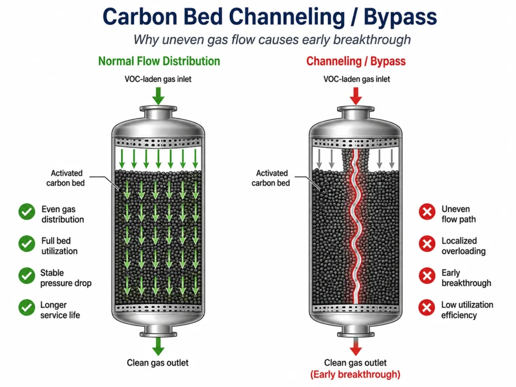
Channeling occurs when part of the gas finds a low-resistance route through or around the bed. Carbon along that route becomes loaded quickly while other sections remain underused.
Common causes include:
- Uneven carbon filling
- Bed settling
- Gaps near vessel walls
- Cracks in the carbon surface
- Damaged support screens
- Poor inlet distribution
- Low carbon fill level
- Mixed particle-size distribution
- Local accumulation of fines
- Leaking doors, seals, dampers or valves
A system affected by channeling may show outlet breakthrough even though much of the installed carbon still has available capacity.
During changeout, take samples from several positions rather than testing only the top layer.
Large differences between the inlet side, outlet side, center and vessel wall may indicate poor gas distribution.
7. Dust, Oil Mist or Overspray Is Fouling the Carbon
Activated carbon cannot perform efficiently when pore entrances are coated or blocked.
Industrial exhaust may contain:
- Paint droplets
- Resin aerosols
- Oil mist
- Tar
- Plasticizers
- Particulate dust
- Condensed high-boiling compounds
- Sticky production by-products
These contaminants may coat pellet surfaces, block pores or cause particles to bind together.
A rising pressure differential combined with falling VOC removal efficiency often indicates:
- Fouling
- Condensation
- Excessive fines
- Bed compaction
Before installing new carbon, inspect the condition and maintenance history of:
- Prefilters
- Demisters
- Bag filters
- Cyclones
- Oil separators
- Spray-booth filters
- Duct drains
- Condensate traps
A higher-activity carbon cannot compensate for ineffective upstream particulate or aerosol control.
8. The Carbon Grade Does Not Match the VOC Duty
CTC activity, iodine number and BET surface area are useful product characteristics, but none can independently predict service life for every VOC stream.
Premature breakthrough may occur when:
- The pore structure does not match the target compounds
- A general odor-control grade is used for heavy solvent loading
- Standard carbon is used for reactive inorganic gases
- Mechanical strength is insufficient
- The media contains excessive fines
- Pellet diameter creates unsuitable pressure drop
- Regenerated carbon has not recovered enough working capacity
- One carbon type is expected to treat incompatible contaminants
A higher CTC number may provide more gas-phase activity, but it does not guarantee a proportional increase in operating life.
Carbon selection should consider:
- VOC composition
- Normal and peak concentration
- Temperature
- Humidity
- Airflow
- Bed dimensions
- Required outlet concentration
- Regeneration strategy
- Pressure-drop limitations
PureStar’s article on selecting activated carbon for industrial VOC treatment explains the information needed for an initial product comparison.
Four-Step Troubleshooting Process
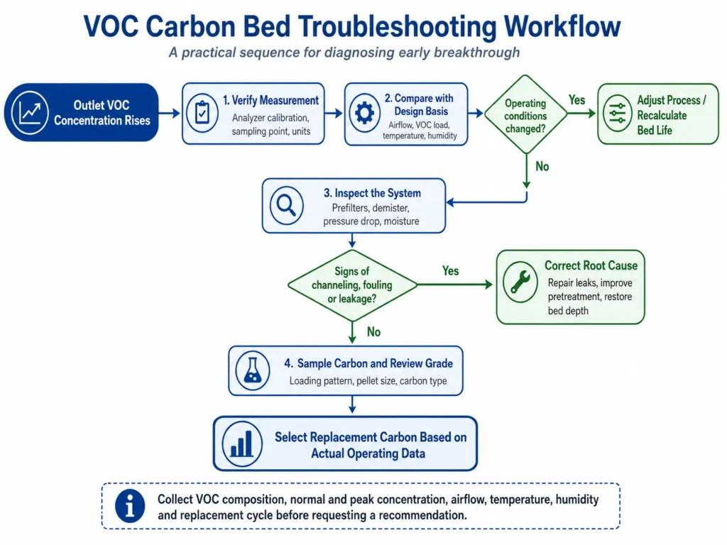
Replacing the whole bed should not be the first diagnostic action.
Step 1: Confirm That Breakthrough Is Real
Verify:
- VOC analyzer calibration
- Sampling location
- Sampling frequency
- Units of measurement
- Laboratory method
- Whether the result represents total VOC or one compound
- Whether inlet and outlet samples were collected under comparable conditions
Odor complaints may justify an inspection, but odor alone is not a reliable measurement of total VOC removal.
Step 2: Compare Current Operation with the Design Basis
Complete a simple comparison table.
| Parameter | Original design | Current normal | Current peak |
|---|---|---|---|
| Airflow | |||
| Inlet VOC concentration | |||
| VOC composition | |||
| Gas temperature | |||
| Relative humidity | |||
| Operating hours per day | |||
| Required outlet concentration |
This often reveals that the adsorber is operating outside its original design conditions.
Step 3: Review Trends and Inspect the System
Trend the following values instead of relying on one measurement:
- Inlet VOC concentration
- Outlet VOC concentration
- Airflow
- Gas temperature
- Bed temperature
- Relative humidity or moisture
- Pressure differential
- Operating hours
Then inspect:
- Prefilters and demisters
- Duct drainage
- Carbon bed depth
- Surface cracks
- Wall gaps
- Supports and distributors
- Seals and bypass dampers
- Wet or agglomerated carbon
- Fines accumulation
Take photographs before removing the media.
Step 4: Sample the Bed and Correct the Root Cause
Where safe and practical, take samples from:
- Inlet section
- Middle section
- Outlet section
- Center of the vessel
- Near the wall
- Any visibly wet or channelled area
The results can help distinguish uniform exhaustion from bypass, fouling or uneven loading.
Correct the system problem before refilling. Depending on the diagnosis, this may require:
- Better cooling
- Improved demisting
- Upgraded filtration
- Repairing leaks
- Correcting gas distribution
- Restoring bed depth
- Reducing peak airflow
- Separating incompatible contaminants
- Changing pellet diameter
- Selecting a different carbon grade
How to Estimate Carbon Bed Life
VOC loading, kg/h = airflow, m³/h × VOC concentration, mg/m³ ÷ 1,000,000
Estimated bed life, h = carbon mass × dynamic working capacity × usable-bed factor ÷ VOC loading
Where:
- Carbon mass is expressed in kilograms
- Dynamic working capacity is expressed as kg VOC/kg carbon
- VOC loading is expressed in kg/h
- Usable-bed factor accounts for incomplete bed utilization
Illustrative Calculation
This example demonstrates the calculation method only. It is not product-design data.
Assume:
- Airflow: 10,000 m³/h
- VOC concentration: 400 mg/m³
- Carbon mass: 2,000 kg
- Estimated dynamic working capacity: 0.15 kg VOC/kg carbon
- Usable-bed factor: 0.70
First calculate the inlet VOC load:
10,000 × 400 ÷ 1,000,000 = 4 kg VOC/h
Then estimate the operating life:
2,000 × 0.15 × 0.70 ÷ 4 = 52.5 operating hours
The result is only a preliminary estimate.
The working-capacity value and usable-bed factor must come from suitable dynamic test data, previous operating experience or a conservative engineering assessment.
The calculation should also consider:
- Concentration peaks
- Mixed-VOC competition
- Humidity
- Temperature
- Required outlet limit
- Bed channeling
- Intermittent production
- Regeneration losses
Do not use CTC activity or equilibrium capacity directly as dynamic working capacity.
Matching PureStar Carbon Grades to VOC Duty
These products are possible starting points, not automatic selections.
| Operating duty | Possible starting grade | Selection consideration |
|---|---|---|
| General industrial VOC and odor control | PL-350/PL-450 50% CTC Coal Columnar Carbon | 3 mm and 4 mm options for standard gas-phase adsorption duties |
| Variable or elevated VOC loading | PL-360/PL-460 60% CTC Enhanced VOC Removal Carbon | Higher activity for applications requiring additional adsorption capacity |
| Demanding solvent recovery and gas purification | PL-380/PL-480 80% CTC Solvent Recovery Carbon | Higher gas-phase activity for more demanding solvent and recovery duties |
Moving from 50% CTC to 60% or 80% CTC does not mean field service life will increase by the same percentage.
Actual performance still depends on working capacity for the target VOC, gas conditions, bed design and operating stability.
Information Needed for a Carbon Recommendation
Provide the following information when investigating premature VOC breakthrough or requesting replacement media:
- Target VOC names
- Approximate VOC composition
- Normal and peak inlet concentration
- Required outlet concentration
- Normal and maximum airflow
- Inlet gas temperature
- Relative humidity or moisture content
- Continuous or intermittent operation
- Operating hours per day
- Adsorber dimensions
- Carbon bed depth
- Current carbon grade and pellet size
- Current carbon quantity
- Actual replacement cycle
- New and final pressure differential
- Presence of dust, oil mist, overspray or condensation
- Existing pretreatment equipment
- Regeneration method, where applicable
- Required order quantity and packaging
Complete operating data makes it possible to recommend a carbon grade for the actual process rather than only comparing activity numbers on a COA.
Frequently Asked Questions
What is the difference between breakthrough and saturation?
Breakthrough occurs when the outlet VOC concentration reaches a defined limit. Saturation is the maximum amount the carbon may hold under specified equilibrium conditions. A carbon bed can therefore reach the replacement point before every pellet is fully saturated.
Does higher CTC always extend carbon bed life?
No. Higher CTC may indicate greater gas-phase activity, but service life also depends on VOC composition, working capacity, temperature, humidity, contact time, bed distribution and outlet requirements.
Can humidity cause early activated carbon breakthrough?
Yes. High moisture may reduce usable capacity for some VOC streams. Condensation can also block gas paths, increase pressure drop and create uneven flow through the bed.
How should carbon adsorber performance be monitored?
Outlet VOC concentration is the most direct performance indicator. It should be evaluated together with inlet VOC load, airflow, gas and bed temperature, moisture, pressure differential and operating time.
Should I choose 3 mm or 4 mm pelletized carbon?
Three-millimeter pellets may support faster mass transfer but generally create more airflow resistance. Four-millimeter pellets normally reduce pressure drop but still require adequate contact time. Selection should be based on the vessel and operating conditions.
Can spent VOC carbon be regenerated?
Some solvent-loaded carbons can be regenerated. Suitability depends on the adsorbed compounds, carbon condition, regeneration method, safety controls and the amount of working capacity recovered after regeneration.
Fix the Cause Before Replacing the Carbon
Activated carbon breakthrough is not always a carbon-quality problem. It is a signal that the media, process conditions or adsorber design no longer support the required removal target.
Before purchasing replacement carbon:
- Verify the outlet measurement.
- Compare current conditions with the original design.
- Review airflow, VOC load, temperature, moisture and pressure-drop trends.
- Inspect pretreatment, seals and bed distribution.
- Correct the root cause.
- Select carbon using actual operating data.
Order & Project Support
Send PureStar your VOC composition, inlet and outlet concentrations, airflow, temperature, humidity, adsorber dimensions, current carbon specifications and actual replacement cycle.
Our team can review the operating conditions and recommend a suitable activity level, pellet diameter and preliminary sample-testing plan.
Contact PureStar for VOC Carbon Selection Support
Technical References
- U.S. EPA – Monitoring by Control Technique: Activated Carbon Adsorber
- U.S. EPA – Air Pollution Control Cost Manual and Carbon Adsorber Guidance
- U.S. EPA – Compliance Assurance Monitoring Guidance for Carbon Adsorbers
- ASTM D4607-14(2021) – Standard Test Method for Iodine Number of Activated Carbon
Final carbon selection should also be based on the product COA, dynamic adsorption test results and actual site operating records.